REFERENCE
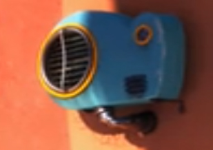 |
| Air Conditioning Unit used for the general shape of the robotic cat's body shape. |
 |
| Specifically the front legs inspired the front legs of the robot cat's front legs. |
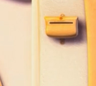 |
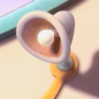
| This mail box inspired the head used for the robot cat's head. |
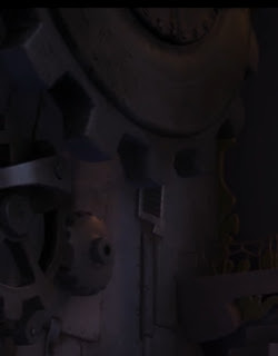 |
| Gears within the movie of "The Lorax" inspired the design of the robot cat's legs. |
How I picked my images...
When choosing references I was not concentrating on picking any one given animal or seekign out robotic creatures. I just turn on the movie, lay back, and let the images create imagination and design possiblities. When I run into shapes or items that are intriguing I pause the movie, rewind, and take a snapshot. As the movie goes on I begin to build the model in my head until I find myself with a complete picture.
CONCEPT SKETCHES (drawn over with sharpie)
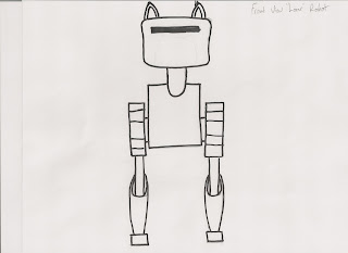 |
| Robot Cat Front View |
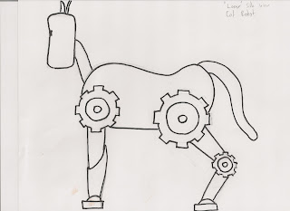 |
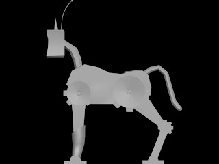
| Robot Cat Side View |
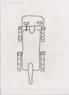 |
| Robot Cat Top View |
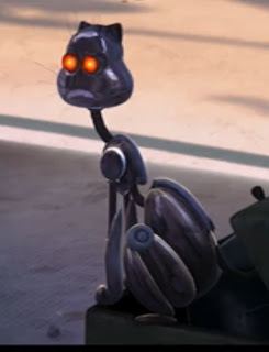
I wasn't sure what kind of robot would be found within the milieu of the movie "The Lorax". I noticed a cat surveillance robot in the movie so I stuck with this concept idea for my game modeled robot. I didn't however want to try to copy what the movie had created so I grabbed other elements and objects found in the movie to create the robot cat. I created the robot from an air conditioner, factory gears, and a mail box. The only part of the original robot cat from the movie I kept was the shape and style of the front legs which I found very unique. In this manner I could create a model that was keeping within the style of the movies concept and design, but keep it unique and original as well.
FIRST PASS MODEL
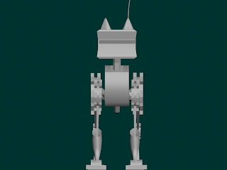 |
| Robot Cat Front View (Rendered in 3DS MAX) |
 |
| Robot Cat Side View (Rendered in 3DS MAX) |
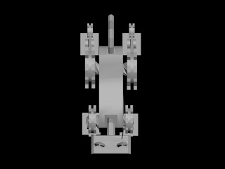 |
| Robot Cat Top View (Rendered in 3DS MAX) |
After practicing conceptual modeling with the helmet and the light fixture I found modeling the robotic cat quite entertaining and easy. I first started with the body by creating a box and moving edges into the general shape of the air conditioning unit found in the movie. After that I made the gears that would attach to the body and connect to the legs. I created these with a cylinder and simply beveled out the faces. I then attached them to the body using the same method I used for the light fixture side lamp parts. I extruded the 4 sided edges of the poly I wanted to connect the gear two. I chamfered the vertices to create 12 vertices and welded the vertices closest to the body down (4) to end up with 8 vertices on the edge loop of the body and the edge loop of the gear. After that I attached the editable polys and target welded them together. The legs were beveled out from the gears and the feet were attached. The feet were made from a cylinder. I cut the cylinder in half and capped off the open side. I then beveled on local norm the face loop on the bottom outside to create the very bottom part of the foot. The head was created with a box and chamfered edges and the ears from a cone that was manipulated using scale and moving the edges. They were connected to the head in the same manner the gears were connected to the body. Over all it was a much longer process than the light fixture and the helmet, but was approached with more understanding after learning the lessons from the last two models.
ANIMATION
Idle Motion (Litter Box)
Walking Animation (First Pass)
Attacking Animation (First Pass)
ANIMATION (Second Pass)
Walking Animation (Second Pass)
Attack Animation (Second Pass)
Animating was fairly difficult. The front two legs have bone rigging and the back two legs are linked and the pivots are centered. The biggest problem in animating the Robot Cat was getting the timing just right on the alternating leg movements of the legs. Alot of times the left rear leg would suddenly move too quickly throwing the smooth alternating action of the legs off. Rigging took about 6 hours to get just right to that animating would be easy. Dummies were used on the front feet so that the feet could be rotated without rotating the bone with it, since without the dummy the pivot of the foot geometry would not move with the foot when moved with the bone. Interestingly the pouncing attack animation was the simplest. The methodology behind it was less about alteranting the legs and more about the forward and upward movement of the body. As well the legs mostly moved together with a slight offest for a more relaxed and natural looking movement of the body.
FINAL RENDER(All Texture Maps)
(Front View)
(Side View)
(Top View)
(Perspective)
FINAL THOUGHTS
After modeling the helmet and the light fixture this model was really easy to design and model. Mostly because the requirement was to make a robotic creature I was able to design it with a more boxy look. this made it much easier to unwrap and texture. As well since the model was a robot I was able to put a simple tilable metal texture as a base. The donw side to this model was keeping the poly count minimal. I ended the model with around 1200 polys. For an entire creature model this isn't too bad, being a non player character in a game it would take far too much space. Being the first model I animated in the series this increased rendering time. As far as the animation goes rigging was fairly easy. How you rig however was quite a pain while first learning. Getting certain IKs connected to the bones in specific spots for desired results took hours of testing and messing around. This was only done with the front legs. To allow the front feet to rotate (rigging the foot with the bones didnt allow it's pivot point to follow) I attached dummies to the feet and linked the dummies to the bones and upper legs. As well by attaching the dummy to the upper leg I was able to get a full range of motion while only moving the IK, rather than selecting multiple IKs increasing the time it would have taken to animate the robot. the rear legs were on rigged. they were linked to the body and each other in subsequent order to the feet. To animate the legs I selected the upper leg, lower leg, and foor and rotated them at the same time independently so that all parts would rotate equally. I alos rigged the tail for minimal movelment. to move the head I selected all the polys of the head, gave them an ID, and when I need to move the head I would select the ID and simply rotate the polys and move them around. Over all this one took the most time due to proper rigging and rendering time, but was the most fun to do. Figuring out ways to get the robot cat to jump was both unique and intriguing. I look forward to doing more animation in the near future, trouble shooting, and learing new tricks of the trade.


.png)


