REFERENCE
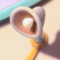 |
| Reference for Main Lamp |
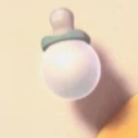 |
| Reference for side bulbs using the added style of the tree lights. (as shown below) |
.png) |
| Artificial Trees (lights) |
How I got my images...
Though there were thousands of light fixture in this movie, they were all extremely similar and unoriginal to one another, and very far away. Getting a good image of a light fixture to use was difficult. So I went with the images of the light fixtures I found to be the least grainy and out of focus and simply attach them together. My end result is a light fixture more similar to the movies', then my other models are. Something I try to avoid, but when required, we do our best.
CONCEPT
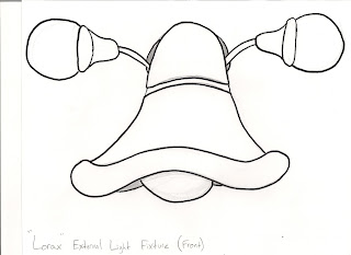 |
| Concept for External Light Design using aspects found in the references above. |
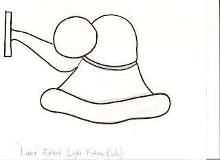 |
| Side View of External Light |
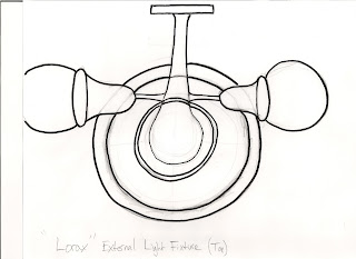 |
| Top View of External Light |
RENDER
 |
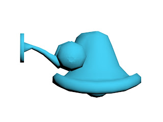
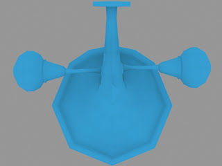
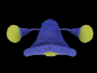
| Model Rendered in 3DS MAX using concept designs as reference (First Pass Front View) |
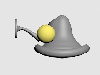 |
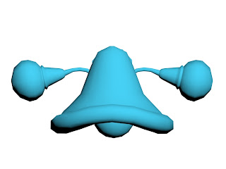
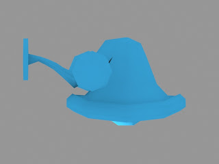
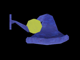
| External Light rendered in 3DS MAX (First Pass Side View) |
 |
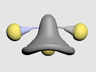
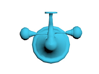
External Light rendered in 3DS MAX (First Pass Top View)
|
From the concept/reference I created the main lamp shape from a sphere. The bottom half of the sphere's poly's were selected and deleted. A Shell modifier was then added and collapsed into an editable poly. The main light bulb in the middle is a normal 16 sided sphere. The vertices were selected and moved to give the rim of the light fixture a lip. The two smaller lights were created with a cylinder that was put on a path deform and collapsed into an editable poly, attached to an 8 sided sphere and welded into a single primitive. The wall attachment was created by beveling from faces off the main lamp shape and welded down to a curve. The cylindrical wall attachment was created using bevel on local normal.
RENDER(Second Pass)
 |
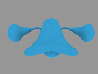
| Low Poly (Right Side) |
 |
| Low Poly (Top View) |
 |
| Low Poly (Front View) |
In the second week it was required to reduce the number of polys into the models most basic shape. In addition the requirement of creating a single mesh rather than multiple primitives. When approaching in this manner it was easier modeling a good end result knowing the end product would be a low poly. The biggest challenge was attaching cylindrical objects to a four sided poly (in order to create a single mesh object). The solution I came up with is to delete the four sided face in which I would attach the cylindrical object. The grab the edge loop of that deleted face and extrude it out and chamfer all vertices of the extruded edges. Then I target welded the vertices to the object and kept 8 vertices. Sine I reduced the number of edges on my cylinder down to 8 it was a perfect fit. I attached the primitves and target welded them together with my new vertices.
UVW LOW POLY REDUCTION
(From 800 polys to just above 400 polys)
 |
| Front View (3DS MAX) |
 |
| Top View Render (3DS MAX) |
 |
Right View Render (3DS MAX)
|
In order to UV unwrap my object I need to reduce the number of polys even more. The most challenging part was reducing the polys around the beveled handle on the main lamp shape. It was even tougher to keep the objects symmetry and edge loops; however, I was able to reduce the polys from 800 down to 400 polys.
UV UNWRAP SCHEME (Not Flattened)
UV UNWRAP (Flattened)
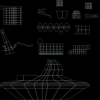 |
| UV Map for Light Fixture (3DS MAX) |
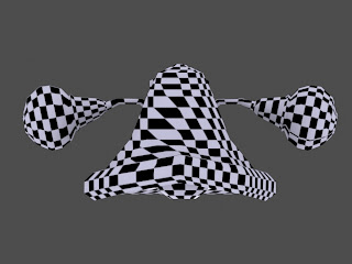 |
| Front view diffuse map (checkered) with UV Unwrap) |
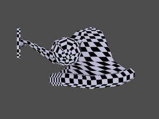 |
| Side view diffuse map (checkered) with UV Unwrap) |
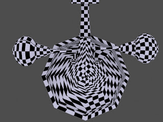 |
| Top view diffuse map (checkered) with UV Unwrap) |
For the first time I unwrapped my light fixture. With the sloping of the main lamp shape and the spheres it was difficult to stitch pieces of the flattened map together and keep the integrity of the texture. In order for me to be able to flatten and stitch and keep the integrity I stitched the the circular polys into a flat rectangular map much like a map of earth. A few places on the object keep a warped or twisted texture, but I will resolve these issues with texture sets. There are few seams that are all on the back end of the light fixture which is good since that is the part facing the wall in real world space. Over all the experience of flattening and stitching was tedious which pushes further the idea of lowering the poly count especially for circular shaped polys.
TEXTURE (First Pass)
Texture Set
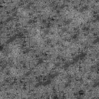 |
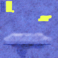
| Texture Set (Top Left) Diffuse, (Top right) Specular, (Bottom) Bump |
UV Unwrap Texture Set
 |
| UV Unwrap Texture Set (Top Left) Diffuse, (Top Right) Specular, (Bottom) Bump |
Textures:
Texturing was done in photoshop. I took my completed flattened UV unwrap and began drawing out my textures. I went to "cgtextures.com" and got a metal rust pictures. I imported it into photoshop as a 512 by 512 photo and copy pasted it it until it filled up my 2048 by 2048 UV unwrap picture. I then made it tilable by offsetting the picture and using the stamp, clone, and patch tool to get rid of repeating patterns and ensure the sides, top, and bottom would match up when tiled in 3DS MAX so that no lines would show up on the textured model. To create the bump map I made my final image in gray scale by using a black and white adjustment layer. The Speculat I used the black and white adjustment layer aswell as the levels layer and curves layer to get rid of the midtones. I saved all three images and applied them to my final model.
First Pass Model
 |
| Front View Render (3DS MAX) |
 |
| Side View Render (3DS MAX) |
 |
| Top View Render (3DS MAX) |
This weeks progress was easy and difficult. Of course as in all things with modeling the difficulty came with not knowing the "tricks of the trade" and making it look good. The simple and fun part was making the actual textures. I really enjoy working in photo shop and manipulating images; however, getting it to match up well with the object is difficult. I simply to an image of rusty metal and used hue and saturation adjustments to get the purple-blue color that is shared with the reference of the lamp from the movie "The Lorax". I painted on a yellow and used curves to make them a bit lighter. I used burn and dodge to get the gradual color contrast between where the fixture would be exposed to the light from the bulbs.
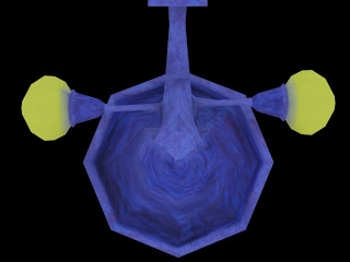
FINAL PASS (diffuse, bump, specular color/level, reflection, and refraction maps all applied)
3DS MAX RENDERS
(Front View)
(Side View)
(Top View)
(Perspective)
FINAL THOUGHTS
After modeling the helmet I approached not the design of the light fixture but the modeling process with low poly in mind. This made for easier UV unwrapping the final model. Though the model isn't as smooth as a new student would expect, it portrays the art in game art. If it was as easy as just making the model with as many polys we wanted and without a water tight mesh, we may just call it engineering. The end result of this model added a few tricks for me when low poly modeling. One of them as stated above was how to connect a circle to a square poly. By chamfering the veritices and ensuring the cylinder I am attaching is 8 sides, I get a perfect fit that can be attached and welded together. Keeping in mind that this creates triangles it's still a fairly decent method. Un wrapping the light fixture was the most difficult part. this being because the light fixture has so many circular surfaces that when flattened create long border edges. this was solved by laying these polys out like squares and expanding the texture out as the polys area shrinks. Limiting cylindrical shapes will be a fore thought before designing future models.
.png)


Building Facade light
ReplyDeleteadds stylish and energy‑efficient illumination to a building’s exterior to enhance its look at night.